Type: Resource
Maint and Constr Management Center
Overview
The 'Maint and Constr Management Center' monitors and manages roadway infrastructure construction and maintenance activities. Representing both public agencies and private contractors that provide these functions, this physical object manages fleets of maintenance, construction, or special service vehicles (e.g., snow and ice control equipment). The physical object receives a wide range of status information from these vehicles and performs vehicle dispatch, routing, and resource management for the vehicle fleets and associated equipment. The physical object participates in incident response by deploying maintenance and construction resources to an incident scene, in coordination with other center physical objects. The physical object manages equipment at the roadside, including environmental sensors and automated systems that monitor and mitigate adverse road and surface weather conditions. It manages the repair and maintenance of both non-ITS and ITS equipment including the traffic controllers, detectors, dynamic message signs, signals, and other equipment associated with the roadway infrastructure. Weather information is collected and fused with other data sources and used to support advanced decision support systems.
The physical object remotely monitors and manages ITS capabilities in work zones, gathering, storing, and disseminating work zone information to other systems. It manages traffic in the vicinity of the work zone and advises drivers of work zone status (either directly at the roadside or through an interface with the Transportation Information Center or Traffic Management Center physical objects.)
Construction and maintenance activities are tracked and coordinated with other systems, improving the quality and accuracy of information available regarding closures and other roadway construction and maintenance activities.
This resource is related to the "Maint and Constr Management Center" physical object.
This resource is included in the following applications:
- Advanced Traveler Information Systems
- Data Distribution
- Eco-Integrated Corridor Management Decision Support System
- Emergency Communications and Evacuation
- Enhanced Maintenance Decision Support System
- Freight-Specific Dynamic Travel Planning
- Incident Scene Pre-Arrival Staging Guidance for Emergency Responders
- Infrastructure Management
- Map Management
- Oversize Vehicle Warning
- Reduced Speed Zone Warning / Lane Closure
- Road Weather Information for Maintenance and Fleet Management Systems
- Road Weather Motorist Alert and Warning
- Vehicle Data for Traffic Operations
- Warnings about Hazards in a Work Zone
- Warnings about Upcoming Work Zone
Coordination
Security
Interfaces Diagram
Alternative Configurations
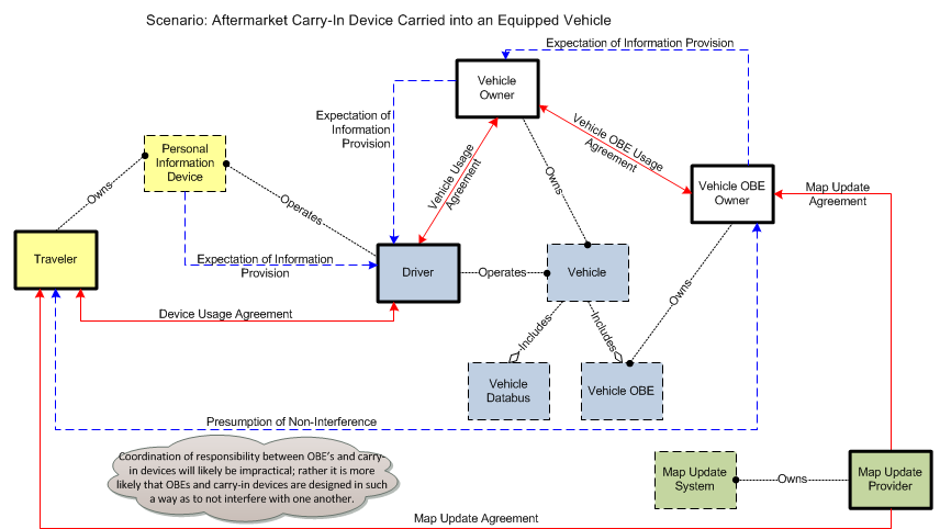
Four diagrams below illustrate four different implementations that may be represented by the Vehicle On-Board Equipment: 1) Vehicle Awareness Device, 2) Aftermarket Device, 3) Retrofit Device, or 4) Integrated System. Each diagram shows the subset of interfaces from CVRIA that are relevant to that particular implementation. Note that a V2V safety application is shown, but the four implementation options also provide varied support for other connected vehicle applications. Map provider shown as it is a likely interface for many safety applications, and the different points at which the map hooks in are illustrative of changes in necessary relationships. A fifth diagram covers a scenario where an aftermarket carry-in device is carried in to a vehicle that is already equipped with one of the Vehicle OBE implementations.
1. Vehicle Awareness Device – This is an aftermarket electronic device, installed in a vehicle without connection to vehicle systems, that is only capable of sending the basic safety message over short range communications. Vehicle awareness devices do not issue audible or visual warnings, alerts, or guidance to the driver of the vehicle.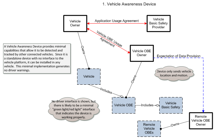
2. Aftermarket Device – This is an aftermarket electronic device, installed in a vehicle, and capable of sending and receiving messages over a wireless communications link. The self-contained device includes GPS, runs connected vehicle applications, and includes an integrated driver interface that issues audible or visual warnings, alerts, and guidance to the driver of the vehicle. The aftermarket device may or may not have access to some vehicle system status.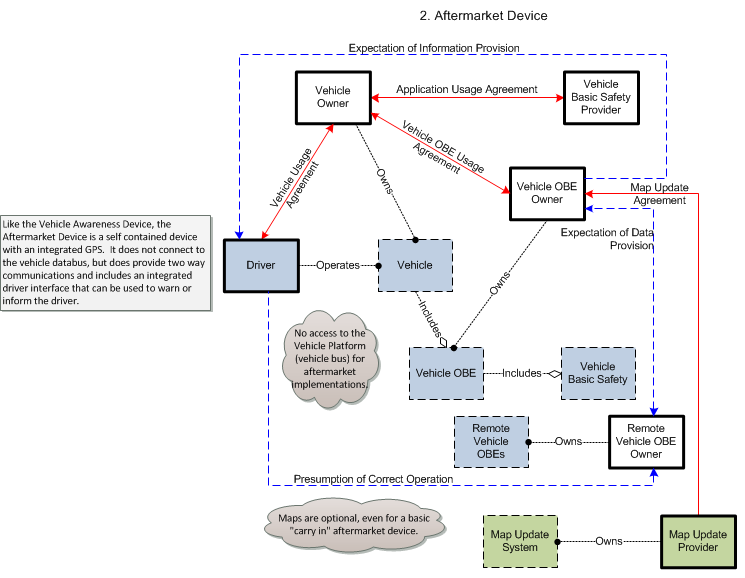
3. Retrofit Device – This is an OEM authorized electronic device installed in vehicles by an OEM authorized service provider, at a service facility after the vehicle has been built. This type of device provides two-way communications and is connected to a vehicle databus. Depending on implementation, the device may include an integrated driver interface and GPS or integrate with modules on the vehicle databus that provide these services. Depending on implementation, it may only support some of the connected vehicle applications identified in CVRIA and potentially support additional applications that are not identified in CVRIA.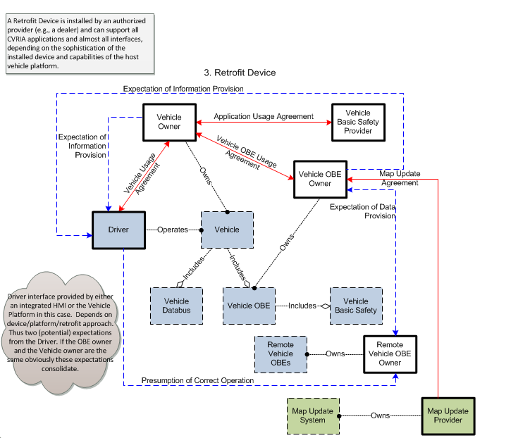
4. Integrated System – This is a system of one or more electronic devices integrated into vehicles during vehicle production. The Integrated System is connected to proprietary data busses to share information with other on-board systems. The Integrated System may be distributed across multiple subsystems and may be configured to support some of the connected vehicle applications identified in CVRIA and potentially support additional applications that are not identified in CVRIA.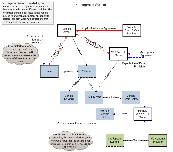
In retrofit and integrated implementations, the Vehicle OBE interfaces to other on-board systems through a vehicle databus (e.g., CAN). Represented in CVRIA as the Vehicle Databus, this interface provides access to on-board sensors, monitoring and control systems, and information systems that support connected vehicle applications. The vehicle databus may also be the source for GPS location and time, map data that supports connected vehicle applications, and the access point for the vehicle's driver-vehicle interface.
5. A fifth diagram covers a scenario where an aftermarket carry-in device is carried in to a vehicle that is already equipped with one of the Vehicle OBE implementations. In this scenario, we have two different devices with possibly two different radios and two different user interfaces that must be coordinated to avoid interference or conflicts.