Physical
The Physical view describes the connections between Physical Objects within the connected vehicle environment.
In this view, the CVRIA is depicted as a set of integrated Physical Objects that interact and exchange information to support the connected vehicle applications. Physical Objects are defined to represent the major physical components of the connected vehicle environment. Physical Objects include Application Objects that define more specifically the functionality and interfaces that are required to support a particular connected vehicle application. Information Flows depict the exchange of information that occurs between Physical Objects and Application Objects. The information exchanges in the Physical View are identified by Triples that include the source and destination Physical Objects and the Information Flow that is exchanged.
At a higher-level, each pair of Application Objects that exchange information flows are also assigned an Application Interconnect or A-Interconnect that represents the entire information exchange for that Application Object pair. For A-Interconnects, the exchanges are defined to include five pieces of information (Quintuples) that include the source Physical Object and Application Object, the destination Physical Object and Application Object, and the A-Interconnect.
The Physical view is related to the other CVRIA Architecture views. Each Application Object is linked to the Functional View, which describes more precisely the functions that are performed and the details of the data that is exchanged by the object. Physical Objects and Application Objects are also linked to the Enterprise view, which describes the organizations that are involved and the roles they play in installing, operating, maintaining, and certifying all of the components of the connected vehicle environment.
In addition, the physical view includes a notional hierarchy. Considering the Connected Vehicle architecture from its most abstract (highest) level, the physical view describes interactions between support, center, field, traveler and vehicle systems as shown in the figure below.
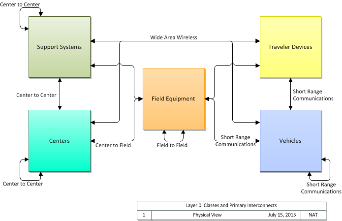
(Note that in this diagram we focus only on the primary interactions between systems; if we consider all possible interactions in the architecture, the connections between systems include more possibilities, as illustrated in this enhanced figure.)
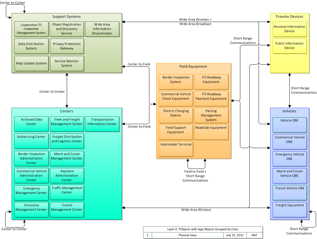
If we zoom in on the physical, we can see what types of objects are contained within the support, center, field, traveler and vehicle systems. We still focus on the primary interconnects, and only include systems that provide application functionality. In the CVRIA, that means that they are either a support system, or contain at least one application object that has an application interconnect to a non-support application object. In other words, these are systems that contribute to the delivery of a user service in at least one CVRIA application.
Finally, if we wish to consider all physical objects in the CVRIA, we can illustrate a comprehensive top level diagram. This diagram separates objects that do not include application functionality and calls them 'terminators', as they serve as either sources or sinks, but not functional elements.